
Crosssection of a typical cantilever retaining wall. Download Scientific Diagram
A cantilever retaining wall is a type of retaining wall that uses a cantilevered structure to resist the lateral pressure of the soil behind it. The wall is typically constructed of reinforced concrete and consists of a horizontal base slab, a vertical stem, and a horizontal top slab, with the base and top slabs connected by a heel at the.
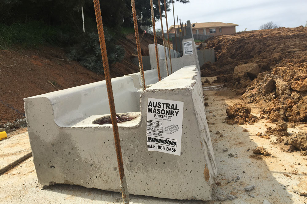
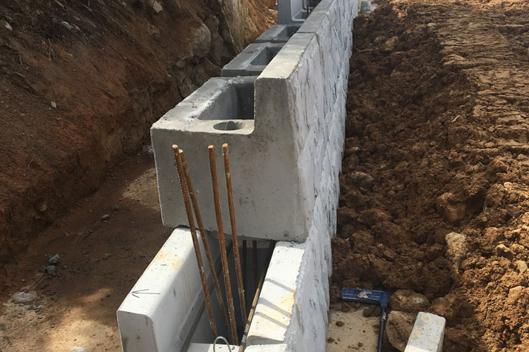
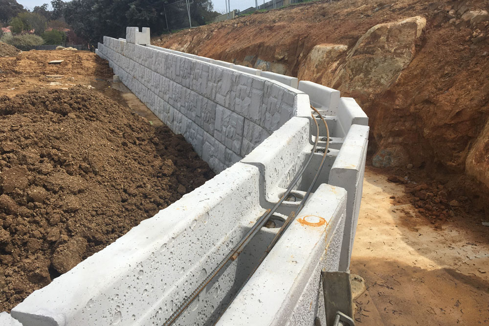
Cantilever Retaining Wall Design MaxumStone
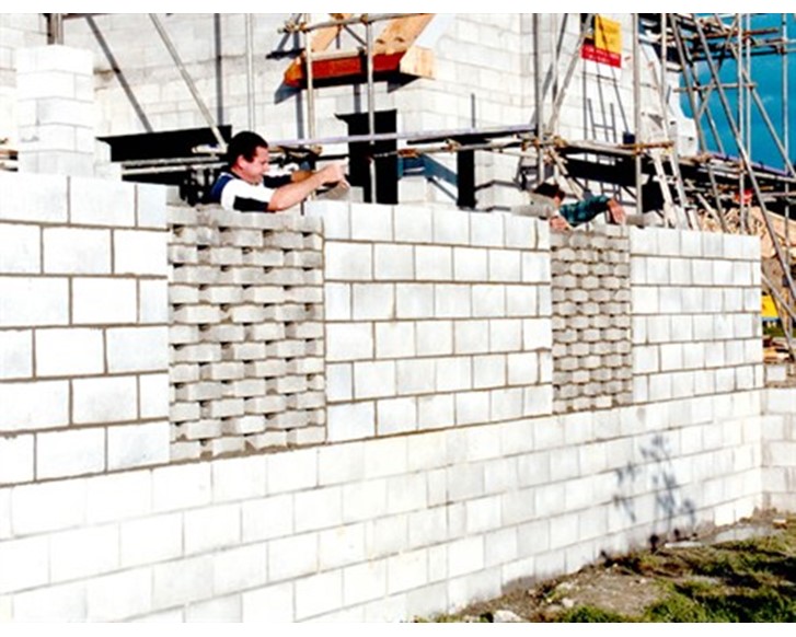
A concrete cantilever retaining wall consists of a reasonably thin vertical stem of steel-reinforced, cast-in-place, concrete or mortared masonry such as CMU blocks. In a cantilever retaining wall style, earth pressure acts horizontally against the side of the wall. The bottom part of the wall counters the earth pressure and pushes back against it.
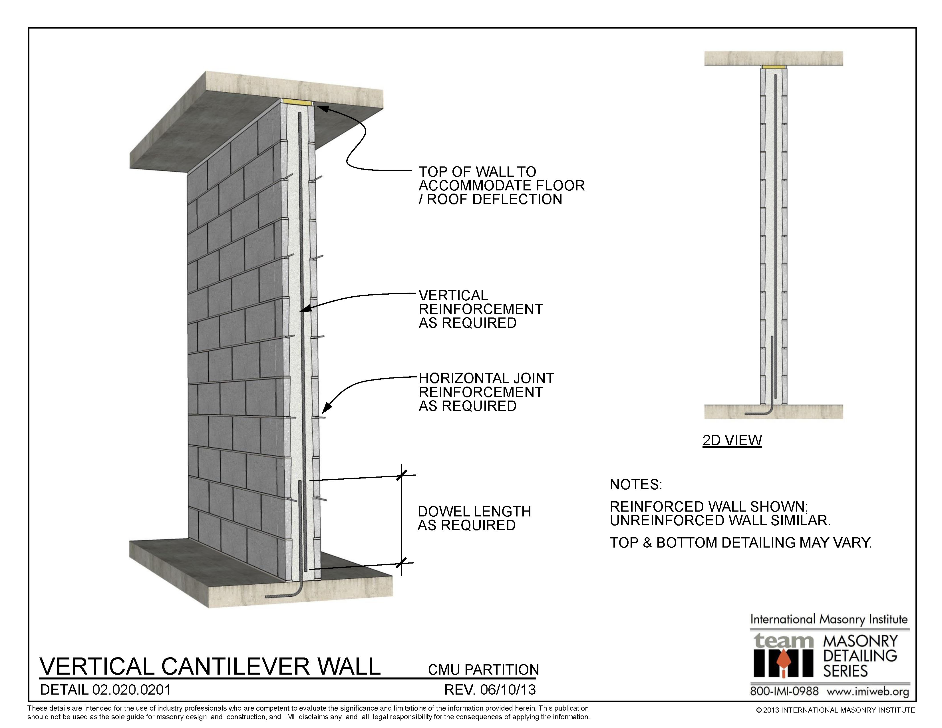
02.020.0201 Vertical Cantilever Wall International Masonry Institute
Cantilever Retaining Wall. Cantilever Retaining Walls are pretty similar to Gravity Retaining Walls, however they include an additional base component that provides additional restraint against overturning and sliding given this additional concrete. This shape is more effective to resist the active forces, as the weight of the active force.

What is Cantilever Retaining Wall? Purpose of Cantilever Retaining wall. Different types of
The cantilever retaining wall has cantilever footings, which have tie beams balancing the asymmetrical load. A counterfort retaining wall is a cantilever wall with counterforts, or buttresses, attached to the inside face of the wall to further resist lateral thrust. Some common materials used for retaining…. Other articles where cantilever.
Cantilever Retaining Wall Design MaxumStone
Parts of Cantilever retaining wall. Stem: It is the vertical upright portion of the cantilever wall which supports or restrain the lateral confinement. The stem has a greater slender ratio. Sometimes the stem is made of the same thickness throughout and sometimes they are made thicker at the base. Toe: it is the base footing embedded on the.
Cantilever Retaining Wall Design MaxumStone
Cantilever retaining wall designs are typically selected and implemented when geogrid and gravity retaining walls are unable to meet the necessary structural criteria. This can be due to a variety of reasons, including right right-of-ways (ROWs) or sites with structures that have extremely close or limited excavation areas.

Cantilever retaining wall with relief shelves in Hyderabad, India Scientific Image
This Example will teach you EVERYTHING about concrete cantilever retaining wall structures! part 1 goes over problem parameters and over turning moment check.
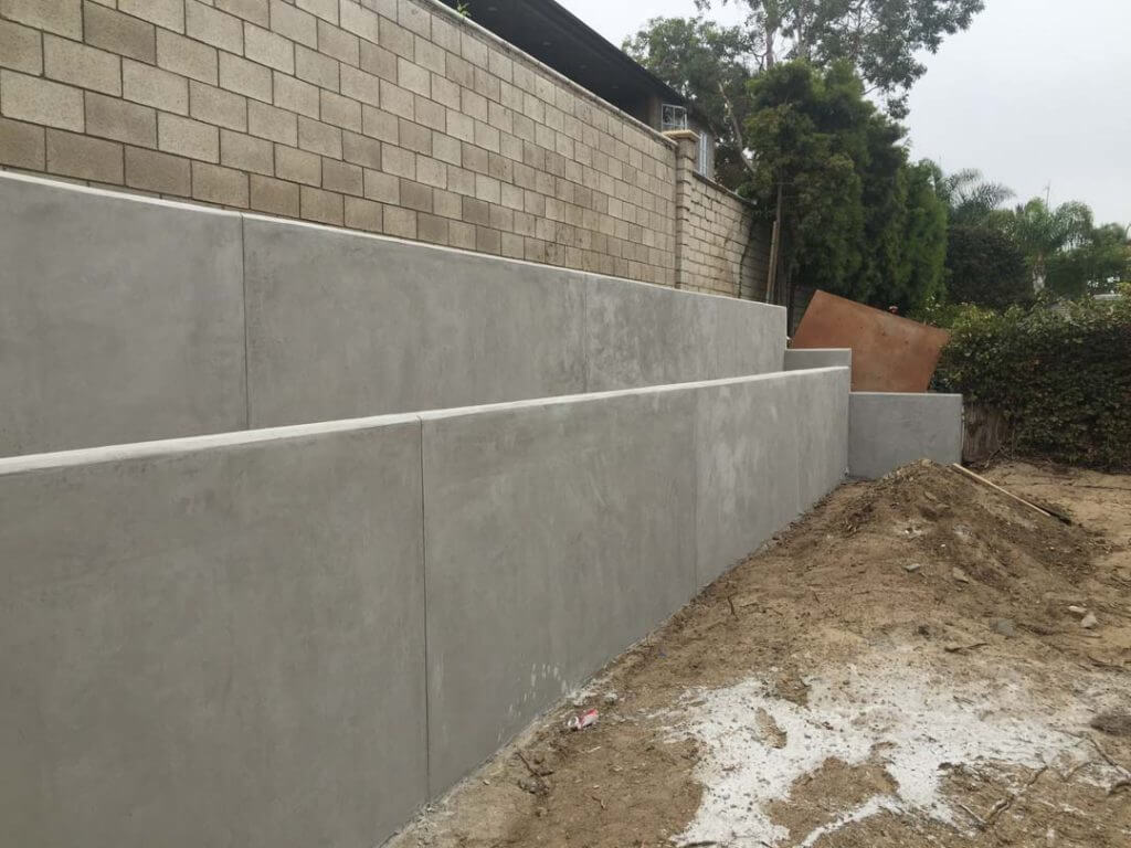
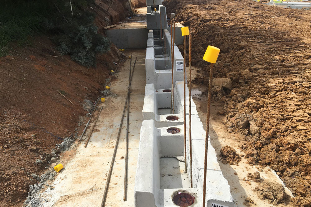
Cantilever Retaining Wall Construction for Wellington Residents
Cantilever retaining wall is the most common type used as retaining walls. Cantilever retaining wall is either constructed on site or prefabricated offsite i.e. precast. The portion of the base slab beneath backfill material is termed as heel, and the other part is called toe. Cantilever retaining wall is economical up to height of 10m.
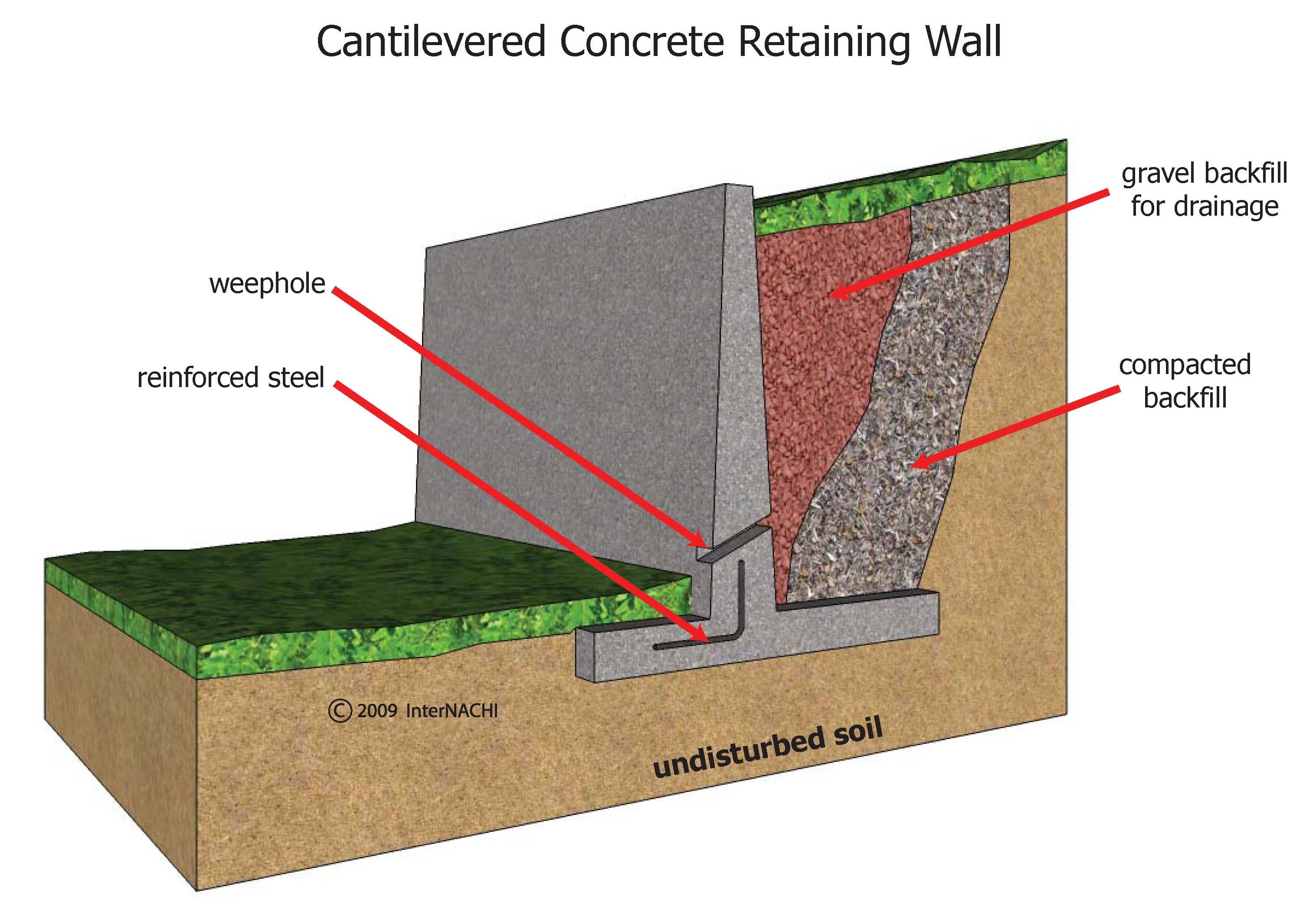
InterNACHI Inspection Graphics Library Exterior » General » cantileveredretainingwall.jpg
Cantilever retaining walls are constructed of reinforced concrete. They consist of a relatively thin stem and a base slab. The base is also divided into two parts, the heel and toe. The heel is the part of the base under the backfill. The toe is the other part of the base. Use much less concrete than monolithic gravity walls, but require more.

Cantilever and Restrained Retaining Wall Design Software SoilStructure Software
Figure A.1-Retaining Wall Cross Section. Consider the cantilever retaining wall with the cross-section shown in the above Figure A.1, which retains a 2m depth of soil having the groundwater table at -1.0m level. Design Parameters: Soil Bearing Capacity, q all : 100 kPa; Coefficient of Soil Friction, ф: 30° Unit Weight of Soil, ɣ s: 18 kN/m 3
Cantilever Retaining Wall Design MaxumStone
Reinforced concrete cantilever retaining walls consist of a relatively thin stem and a base slab. The stem may have constant thickness along the length or may be tapered based on economic and construction criteria. The base is divided into two parts, the heel and toe. The heel is the part of the base under the backfill.
Cantilever and Restrained Retaining Wall Design Software SoilStructure Software
Cantilever walls are reinforced concrete and have an L-shaped or inverted T-shaped base. The vertical tension behind the wall is transmitted to the foundation, preventing it from collapsing as a result of lateral earth pressure from the same soil mass. A T-shaped foundation also benefits from the weight of the earth (and hence vertical tension.
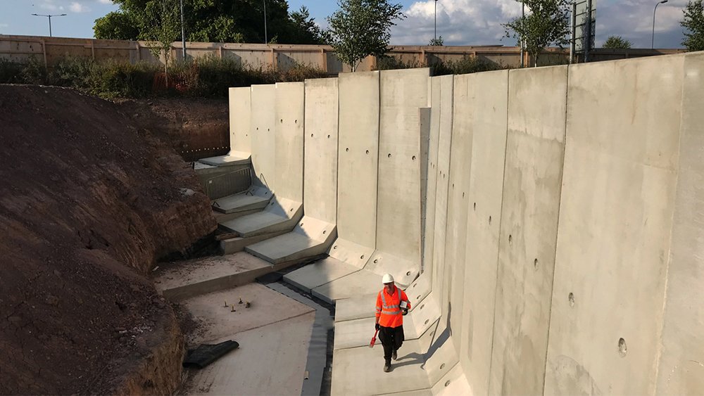
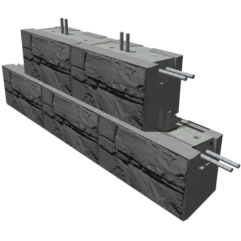
Modular Cantilever Retaining Walls JP Concrete
Cantilever concrete retaining walls are commonly used for residential purposes, often as integral basement walls. Usually the cantilever wall stem is of concrete block construction rising from an in-situ concrete foundation. The following worked example is for a free-standing cantilever wall that is considered
Cantilever Retaining Wall Design MaxumStone
Reinforced concrete cantilever retaining walls consist of a relatively thin stem and a base slab. The stem may have constant thickness along the length or may be tapered based on economic and construction criteria. The base is divided into two parts, the heel and toe. The heel is the part of the base under the backfill.
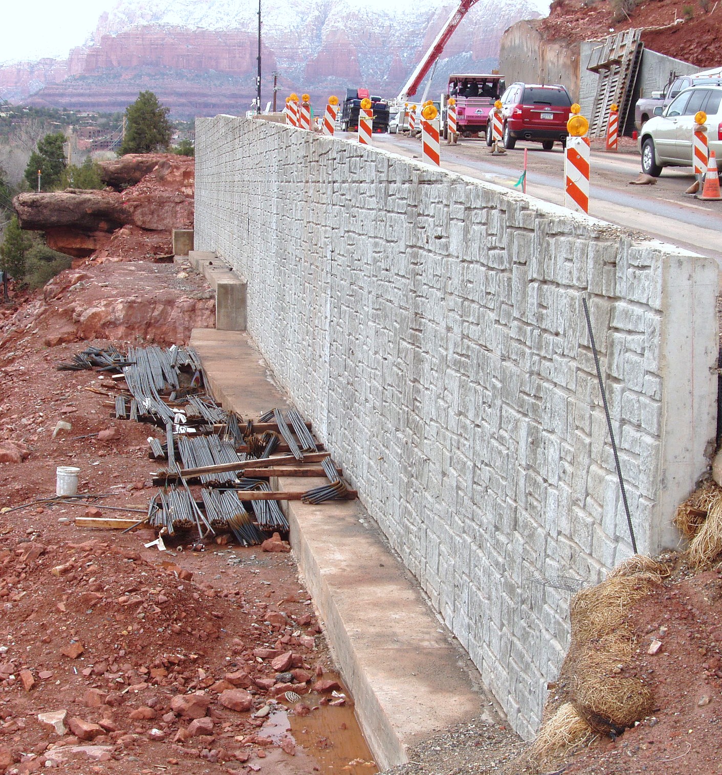
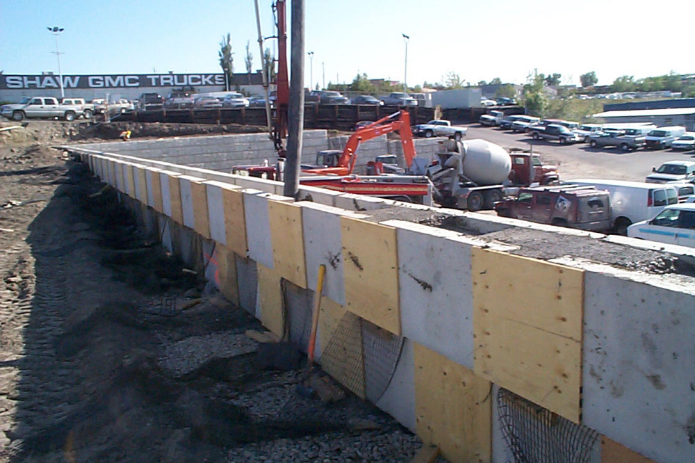
Cantilever Retaining Walls
Cantilever retaining walls have been widely used in construction for decades and have proven to be a versatile and efficient solution for stabilizing earth. This type of retaining wall is designed to resist lateral pressure from retained soil, creating a transition between two different levels of ground. With its unique design and engineering.
Cantilever Retaining Wall Design MaxumStone
Recommended stem designs for reinforced cantilever retaining walls with no surcharge are contained in Tables 1 and 2 for allowable stress design and strength design, respectively. These design methods are discussed in detail in Allowable Stress Design of Concrete Masonry, TEK 14-7A, and Strength Design of Concrete Masonry, TEK 14-4A (refs. 5, 6
